
Page 24 - Gear Technology Solutions
P. 24
Case 1 – No CMM Coordinate File Available
If the Dimension-Sheet calculation is started without the presence of a CMM
coordinate file for this job, then the tooth thickness section in the Dimension-
Sheet will display the following message, also shown at the bottom of Figure 5:
Case 2 – Standard CMM Coordinate File Available
In this case a download file with a grid as it is shown in Figure 7 is available at
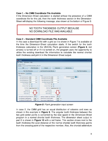
the time the Dimension-Sheet calculation starts. If the switch for the tooth
thickness calculation in the UNICAL Flank generation screen (Figure 8, red
arrows) is turned off or if it is turned on, the program uses the opportunity to
utilize the existing download file information to calculate the normal chordal
tooth thickness and print it in the Dimension-Sheet output.
Figure 8: Flank generation input screen
In case 2, the CMM grid has an equal distribution of columns and rows as
shown in the example in Figure 9. The angular tooth thickness between the
two grid center points is converted by the new applet in the Dimension-Sheet
program in a normal chordal tooth thickness. The dimension sheet output in
part 6 is shown in Figure 10 with a red frame. This section shows next to the
tooth thickness the axial distance of the normal chordal tooth thickness points
from the crossing point of the respective member. Also, the chordal addendum
9