
Page 23 - Gear Technology Solutions
P. 23
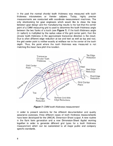
In  the  past  the  normal  chordal  tooth  thickness  was  measured  with  tooth
                   thickness  micrometers  or  Vernier  calipers.  Today,  highly  precise
                   measurements  are  conducted  with  coordinate  measurement  machines.  The
                   only  shortcoming  for  gear  engineers  which  would  like  to  close  the  loop
                   between gear design and the manufacturing results is the fact that the center
                   point of a CMM measuring grid is used to determine the tooth thickness angle
                   between the two flanks of a tooth (see Figure 7). If the tooth thickness angle
                   (in radiant) is multiplied by the radius value of the grid center point, then the
                   circular  tooth  thickness  in  the  approximate  transverse  direction  is  the  result.
                   Due to often different edge reduction at toe and heel as well as top and root,
                   the grid center point is neither exactly at midface nor in the center of the tooth
                   depth.  Thus,  the  point  where  the  tooth  thickness  was  measured  is  not
                   matching the mean face pitch line location.


                                     Figure 7: CMM tooth thickness measurement

                   In  order  to  present  solutions  for  the  different  documentation  and  quality
                   assurance  purposes,  three  different  cases  of  tooth  thickness  measurements
                   have been developed for the UNICAL Dimension-Sheet output. A new routine
                   in  the  flank  form  generation  and  a  new  Dimension-Sheet  Applet  working
                   together  in  order  to  generate  different  grid  types  for  a  tooth  thickness
                   measurement  which  can  be  customized  to  all  major  public  and  company
                   specific standards.


                   8