
Page 30 - Gear Technology Solutions
P. 30
1.9 Precise Calculation of Normal Chordal Thickness
After the software which controls the location of the CMM measurement points
was written, it was only possible to obtain the angular tooth thickness based on
the correct reference point. The steps to convert this flank generation i.e.
measurement result into the normal chordal tooth thickness are conducted in
the Dimension-Sheet applet THKDATA. The first step is the conversion of the
tooth thickness angle DEDI into the transverse chordal tooth thickness DED1,2
with the following calculation:
DED1,2 = 2 * (Coordinate Radius) * sin(DEDI/2)
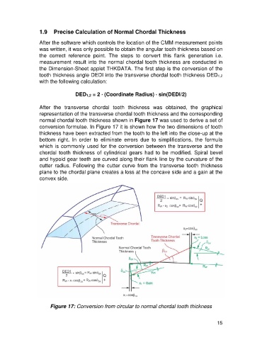
After the transverse chordal tooth thickness was obtained, the graphical
representation of the transverse chordal tooth thickness and the corresponding
normal chordal tooth thickness shown in Figure 17 was used to derive a set of
conversion formulae. In Figure 17 it is shown how the two dimensions of tooth
thickness have been extracted from the tooth to the left into the close-up at the
bottom right. In order to eliminate errors due to simplifications, the formula
which is commonly used for the conversion between the transverse and the
chordal tooth thickness of cylindrical gears had to be modified. Spiral bevel
and hypoid gear teeth are curved along their flank line by the curvature of the
cutter radius. Following the cutter curve from the transverse tooth thickness
plane to the chordal plane creates a loss at the concave side and a gain at the
convex side.
Figure 17: Conversion from circular to normal chordal tooth thickness
15