
Page 22 - Gear Technology Solutions
P. 22
1.8 Tooth Thickness Calculation and Output
International and national standards offer strength calculations for spiral bevel
and straight bevel gears, most of which use the tooth thickness at the pitch
point. The pitch point or calculation point is defined in the standards at the
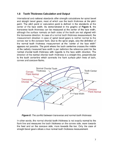
center of the face width. As demonstrated in the graphic of Figure 6, the
transverse tooth thickness can be measured at the center of the face width,
although the surface normals on both sides of the tooth are not aligned with
the transverse direction. In case of a normal tooth thickness measurement, the
measurement direction in case of spiral bevel gears is neither normal to the
convex nor to the concave flank. Due to the spiral angle, also the definition of
the normal tooth thickness measurement at the “center of the face width”
appears not possible. The point where the tooth centerline crosses the middle
of the radially measured face width is per definition the reference point for the
normal chordal tooth thickness with regards to the face width direction. The
direction of the normal chordal tooth thickness is a straight line, perpendicular
to the tooth centerline which connects the flank surface pitch lines of both,
convex and concave flanks.
Figure 6: The conflict between transverse and normal tooth thickness
In other words, the normal chordal tooth thickness is not exactly normal to the
flank line and measures the tooth thickness on the convex side, more towards
the heel and on the concave side, more towards the toe. Only the case of
straight bevel gears allows a true normal tooth thickness measurement.
7