
Page 21 - Gear Technology Solutions
P. 21
1.7 Bearing Loads in Axial and Separating Direction
First, the results of bearing and housing loads created from a newly designed
gearset can be obtained by employing the axial and separating factors from
the Dimension-Sheet. This output was in the past not available in the UNICAL
Dimension-Sheet.
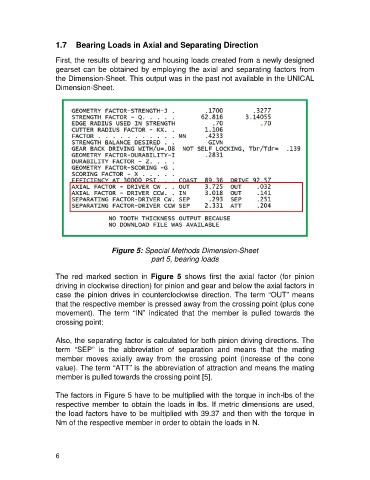
Figure 5: Special Methods Dimension-Sheet
part 5, bearing loads
The red marked section in Figure 5 shows first the axial factor (for pinion
driving in clockwise direction) for pinion and gear and below the axial factors in
case the pinion drives in counterclockwise direction. The term “OUT” means
that the respective member is pressed away from the crossing point (plus cone
movement). The term “IN” indicated that the member is pulled towards the
crossing point:
Also, the separating factor is calculated for both pinion driving directions. The
term “SEP” is the abbreviation of separation and means that the mating
member moves axially away from the crossing point (increase of the cone
value). The term “ATT” is the abbreviation of attraction and means the mating
member is pulled towards the crossing point [5].
The factors in Figure 5 have to be multiplied with the torque in inch-lbs of the
respective member to obtain the loads in lbs. If metric dimensions are used,
the load factors have to be multiplied with 39.37 and then with the torque in
Nm of the respective member in order to obtain the loads in N.
6