
Page 129 - Gear Technology Solutions
P. 129
9.7 Surface Stress and Root Bending Comparison -
Cut versus Forged
®
A root bending stress and surface stress comparison between Coniflex Pro cut
and forged gears was performed with the ANSYS Finite Element Method. The
®
Coniflex Pro differential gearset was designed to replace the originally forged
version. STEP files of the cut and forged version had been converted to the
ANSYS native format. Also, a model of the side gear spline was created, and the
input torque was transmitted from the splined shaft via the internal spline in the
side gear bore to the side gear teeth. A rotational constraint was applied to the
planetary pinion in order to create the reaction torque.
®
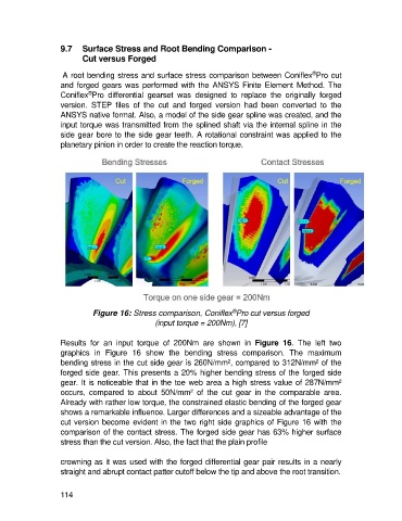
Figure 16: Stress comparison, Coniflex Pro cut versus forged
(input torque = 200Nm), [7]
Results for an input torque of 200Nm are shown in Figure 16. The left two
graphics in Figure 16 show the bending stress comparison. The maximum
bending stress in the cut side gear is 260N/mm², compared to 312N/mm² of the
forged side gear. This presents a 20% higher bending stress of the forged side
gear. It is noticeable that in the toe web area a high stress value of 287N/mm²
occurs, compared to about 50N/mm² of the cut gear in the comparable area.
Already with rather low torque, the constrained elastic bending of the forged gear
shows a remarkable influence. Larger differences and a sizeable advantage of the
cut version become evident in the two right side graphics of Figure 16 with the
comparison of the contact stress. The forged side gear has 63% higher surface
stress than the cut version. Also, the fact that the plain profile
crowning as it was used with the forged differential gear pair results in a nearly
straight and abrupt contact patter cutoff below the tip and above the root transition.
114