
Page 127 - Gear Technology Solutions
P. 127
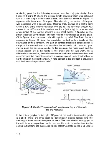
A  starting  point  for  the  following  example  was  the  conjugate  design  from
                   Figure 9. Figure 14 shows the circular length  crowning which was achieved
                   with  a  3°  dish  angle  of  the  cutter  blades.  The  Ease-Off  shown  in  Figure  14
                   represents the flank area of the gear. The relief along the topland of the gear
                   was  generated  with  a  second  order  Modified  Roll,  starting  at  a  profile  point
                   which is 10% of the whole depth away from the tip. The correction amount was
                   chosen to be .020mm with its maximal amplitude (at the tip). In order to avoid
                   a  weakening  of  the  root  by  selecting  a  root  relief  motion,  a  tip  relief  on  the
                   pinion tooth was used instead. The root relief of .030mm labeled on the Ease-
                   Off in Figure 14 was achieved only with a pinion tip relief. The Tooth Contact
                   graphics  in  Figure  14  show  the  calculated  contact  pattern  inside  of  the
                   boundaries of the gear tooth. The path of contact direction is perpendicular to
                   the  pitch  line  (neutral  bias)  and  therefore  the  roll  motion  of  pinion  and  gear
                   moves  along  the  conjugate  profile.  In  this  example,  the  mean  point  and  the
                   contact  pattern  are  in  the  middle  of  the  profile  and  the  face  width.  For  a
                   differential transmission, the deflections under load have to be determined and
                   a  contact  position  correction  ensures  a  contact  spread  under  load  without  a
                   hard contact at the heel boundary. A hard contact at top and root is prevented
                   with the kinematic tip and root relief.


                                               ®
                          Figure 14: Coniflex Pro gearset with length crowning and kinematic
                                                     top and root relief

                   In the bottom graphic on the right of Figure 14, the motion transmission graph
                   is  plotted.  There  are  three  identical  transmission  graphs  representing  the
                   meshing of three consecutive pairs of teeth. The transmission error graph in
                   the middle for example has  nearly zero  amplitudes  in  its  midsection.  As  the
                   contact is transferred to the preceding pair of teeth, a motion error of 25 mrad is


                   112