
Page 124 - Gear Technology Solutions
P. 124
radius. The small amount of depth increase in the center of the face width
increases the tooth thickness which dominates the effect from the larger tooth
depth at the center. As a result, the curved Coniflex root line reduces the bending
stress compared to a straight root line which has been confirmed in practical tests.
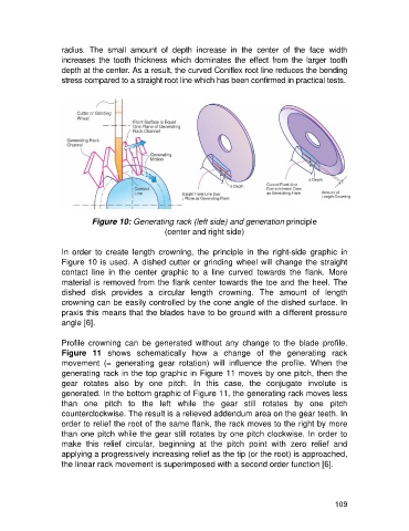
Figure 10: Generating rack (left side) and generation principle
(center and right side)
In order to create length crowning, the principle in the right-side graphic in
Figure 10 is used. A dished cutter or grinding wheel will change the straight
contact line in the center graphic to a line curved towards the flank. More
material is removed from the flank center towards the toe and the heel. The
dished disk provides a circular length crowning. The amount of length
crowning can be easily controlled by the cone angle of the dished surface. In
praxis this means that the blades have to be ground with a different pressure
angle [6].
Profile crowning can be generated without any change to the blade profile.
Figure 11 shows schematically how a change of the generating rack
movement (= generating gear rotation) will influence the profile. When the
generating rack in the top graphic in Figure 11 moves by one pitch, then the
gear rotates also by one pitch. In this case, the conjugate involute is
generated. In the bottom graphic of Figure 11, the generating rack moves less
than one pitch to the left while the gear still rotates by one pitch
counterclockwise. The result is a relieved addendum area on the gear teeth. In
order to relief the root of the same flank, the rack moves to the right by more
than one pitch while the gear still rotates by one pitch clockwise. In order to
make this relief circular, beginning at the pitch point with zero relief and
applying a progressively increasing relief as the tip (or the root) is approached,
the linear rack movement is superimposed with a second order function [6].
109