
Page 123 - Gear Technology Solutions
P. 123
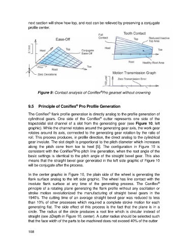
next section will show how top, and root can be relieved by preserving a conjugate
                   profile center.


                                                                  ®
                          Figure 9: Contact analysis of Coniflex Pro gearset without crowning


                                                   ®
                   9.5  Principle of Coniflex  Pro Profile Generation

                                 ®
                   The Coniflex  flank profile generation is directly analog to the profile generation of
                                                                  ®
                   cylindrical  gears.  One  side  of  the  Coniflex   cutter  represents  one  side  of  the
                   trapezoidal  slot  channel of  a  slot  from the  generating gear  (see Figure 10, left
                   graphic). While the channel rotates around the generating gear axis, the work gear
                   rotates around its axis, connected to the generating gear rotation by the ratio of
                   roll. This process produces, in profile direction, the direct analog to the cylindrical
                   gear involute. The slot depth is proportional to the pitch diameter which increases
                   along  the  pitch  cone  from  toe  to  heel  [5].  The  configuration  in  Figure  10  is
                                                ®
                   consistent with the Coniflex Pro pitch line generation, when the root angle of the
                   basic settings is identical to the pitch angle of the straight bevel gear. This also
                   means that the straight bevel gear generated in the left side graphic of Figure 10
                   will be conjugate after the process.

                   In the center graphic in Figure 10, the plain side of the wheel is generating the
                   flank surface analog to the left side graphic. The wheel has line contact with the
                                                                                                        ®
                   involute  flank  surface  at  any  time  of  the  generating  process.  The  Coniflex
                   principle of a rotating plane generating the flank profile without any oscillation or
                   stroke  motion  revolutionized  the  manufacturing  of  straight  bevel  gears  in  the
                   1940’s. The cutting time of an average straight bevel gear was reduced to less
                   than 10% of other processes which required a complete stroke motion for each
                   generating flat. The side effect of this process is the fact that the plane is in a
                   circle.  The  radius  of  the  circle  produces  a  root  line  which  is  circular  instead  of
                   straight (see DDepth in Figure 10, center). A cutter radius should be selected such
                   that the face width of the parts to be machined does not exceed 40% of the cutter


                   108