
Page 122 - Gear Technology Solutions
P. 122
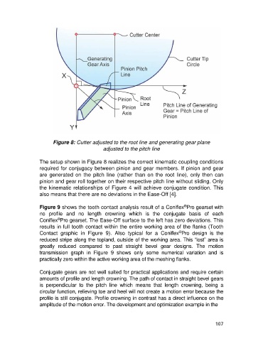
Figure 8: Cutter adjusted to the root line and generating gear plane
                                                 adjusted to the pitch line

                   The setup shown in Figure 8 realizes the correct kinematic coupling conditions
                   required for conjugacy between pinion and gear members. If pinion and gear
                   are  generated  on  the  pitch  line  (rather  than  on  the  root  line),  only  then  can
                   pinion and gear roll together on their respective pitch line without sliding. Only
                   the kinematic relationships of Figure 4 will achieve conjugate condition. This
                   also means that there are no deviations in the Ease-Off [4].

                                                                                       ®
                   Figure 9 shows the tooth contact analysis result of a Coniflex Pro gearset with
                   no  profile  and  no  length  crowning  which  is  the  conjugate  basis  of  each
                            ®
                   Coniflex Pro gearset. The Ease-Off surface to the left has zero deviations. This
                   results in full tooth contact within the entire working area of the flanks (Tooth
                                                                                    ®
                   Contact  graphic  in  Figure  9).  Also  typical  for  a  Coniflex Pro  design  is  the
                   reduced stripe along the topland, outside of the working area. This “lost” area is
                   greatly  reduced  compared  to  past  straight  bevel  gear  designs.  The  motion
                   transmission  graph  in  Figure  9  shows  only  some  numerical  variation  and  is
                   practically zero within the active working area of the meshing flanks.

                   Conjugate gears are not well suited for practical applications and require certain
                   amounts of profile and length crowning. The path of contact in straight bevel gears
                   is  perpendicular  to  the  pitch  line  which  means  that  length  crowning,  being  a
                   circular function, relieving toe and heel will not create a motion error because the
                   profile is still conjugate. Profile crowning in contrast has a direct influence on the
                   amplitude of the motion error. The development and optimization example in the


                                                                                                     107