
Page 77 - Gear Technology Solutions
P. 77
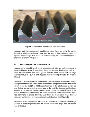
Figure 7: Visible root interference lines and steps

                   It appears as if the interference lines at the right-side flanks are within the starting
                   fillet radius, which the right-side blade was not able to finish because it was not
                   adjusted deep enough. This blade and machine setup error caused the typical in-
                   terference as shown in Figure 5.


                   5.5  The Consequences of Interference

                   It  appears  that  straight  bevel  gears,  manufactured  with  two-tool  generators  as
                   shown in Figures 4 and 7 have been designed with their blade edge radii at or
                   above the interference limit. Although the root fillet looks cleaner with the larger
                   blue fillet radius in Figure 5 and suggests higher bending strength, the reality is
                   different.

                   The result of an interference is often failure after many service hours of a straight
                   bevel gear transmission. Some small interferences can polish out and “heal them-
                   selves” during the first 20 to 100 hours of service.  If the interference is more se-
                   vere, first scratches within the upper area of the root fillet become visible after a
                   break-in  of  the  gearset.  During  some  fraction  of  the  calculated  lifetime  of  the
                   gearset, the scratches will initiate the population of hair cracks in the case depth,
                   most  commonly  in  profile  direction.  Over  time,  the  load  cycles  make  the  hair
                   cracks grow which results in some cases in tooth fracture (see Figure 8).

                   What looks like a smooth and fully rounded root radius can reduce the strength
                   and lead to a catastrophic failure if the chosen radius was larger than the interfer-
                   ence limit radius.


                   62