
Page 72 - Gear Technology Solutions
P. 72
5 Root Interference
5.1 Dimension Sheet Analysis of Root Fillet
On the first page of the Gleason Dimension Sheet for bevel gears, the section be-
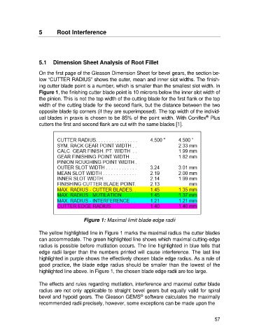
low “CUTTER RADIUS” shows the outer, mean and inner slot widths. The finish-
ing cutter blade point is a number, which is smaller than the smallest slot width. In
Figure 1, the finishing cutter blade point is 10 microns below the inner slot width of
the pinion. This is not the top width of the cutting blade for the first flank or the top
width of the cutting blade for the second flank, but the distance between the two
opposite blade tip corners (if they are superimposed). The top width of the individ-
®
ual blades in praxis is chosen to be 85% of the point width. With Coniflex Plus
cutters the first and second flank are cut with the same blades [1].
Figure 1: Maximal limit blade edge radii
The yellow highlighted line in Figure 1 marks the maximal radius the cutter blades
can accommodate. The green highlighted line shows which maximal cutting-edge
radius is possible before mutilation occurs. The line highlighted in blue tells that
edge radii larger than the numbers printed will cause interference. The last line
highlighted in purple shows the effectively chosen blade edge radius. As a rule of
good practice, the blade edge radius should be smaller than the lowest of the
highlighted line above. In Figure 1, the chosen blade edge radii are too large.
The effects and rules regarding mutilation, interference and maximal cutter blade
radius are not only applicable to straight bevel gears but equally valid for spiral
®
bevel and hypoid gears. The Gleason GEMS software calculates the maximally
recommended radii precisely, however, some exceptions can be made upon the
57