
Page 74 - Gear Technology Solutions
P. 74
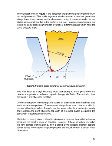
The mutilation lines in Figure 4 are typical for straight bevel gears machined with
                   two tool generators. The blade segments which are used in two tool generators
                   always have sharp corners on the clearance side tip. It is recommended to use
                   blades with a small overlap in the center of the root. However, manufacturers like
                   to use the same blade segments for a variety of different designs which have the
                   same pressure angle.


                              Figure 3: Sharp blade clearance corner causing mutilation

                   This often leads to a large blade top width overlapping up to the point where the
                   clearance edge cuts scratches or ridges in the opposite flanks. The mutilation lines
                   are found in and above the root fillet.

                   Coniflex cutting with interlocking solid cutters on older cradle style machines also
                   leads to the same problem. These cutters always have sharp clearance side tip
                   corners without any radius. Trying to use the same cutter for a certain job variety
                   often exceeds the point where the top width of the cutter blades is equal to the
                   point width (equal slot bottom width).

                   Mutilation commonly does not lead to interference because the mutilation lines or
                   scratches represent a stock off condition. However, if these scratches are within
                   the flank surface working profile, then a sliding of the opposite member topland
                   corner across the scratches might be possible and would result in a certain mesh
                   disturbance.


                                                                                                      59