
Page 82 - Gear Technology Solutions
P. 82
Reducing or eliminating kinematic or physical undercut can be achieved with an
increased pressure angle or a larger profile shift. However, restrictions regarding
pressure angle or profile shift exist, because both reduce the topland thickness
and the root width.
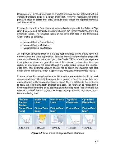
In order to come to a final choice of suitable blade edge radii the Table in Fig-
ure 14 was created. Basically, it shows following the recommendations from the
dimension sheet. The smallest radius of the three limit radii in the Dimension
Sheet should be selected:
· Maximal Radius Cutter Blades
· Maximal Radius Mutilation
· Maximal Radius Interference
An important additional criterion is the top root clearance which should have the
same value as the blade edge radius. Because the maximal permissible edge radii
®
are mostly different for pinion and gear, the Coniflex Pro software has separate
input values for pinion and gear clearance. If the clearance is lower than the edge
radius, an interference will occur although the edge radius is below the interfer-
ence limit. The clearance amount should not be below the maximal root fillet
height shown in Figure 5, which is approximately equal to the blade edge radius.
In some cases, for strength reasons, or because the same cutter should be used
across a variety of different job designs, the edge radius has to be larger than rec-
ommended in the Dimension sheet and in Figure 14. The solution to this conflict is
to apply top relief on the teeth of pinion and gear. Top relief can be realized by a
simple topland chamfering or by applying a kinematic top relief. The kinematic top
®
relief for Coniflex Pro is integrated in the generating cycle and requires no addi-
tional machining time.
Figure 14: Final choice of edge radii and clearance
67