
Page 79 - Gear Technology Solutions
P. 79
ture as shown in Figure 9 is independent from an interference problem. However,
because interferences and root transition steps have been observed together on
the same gears or pinions, it should alert gear engineers when root transition
steps are recognized. Steps and fins at the bottom of the root are rather harmless.
They are far enough away from the 30° tangent and are merely an esthetic dis-
turbance.
®
5.6 Straight Bevel Gears with Coniflex Plus
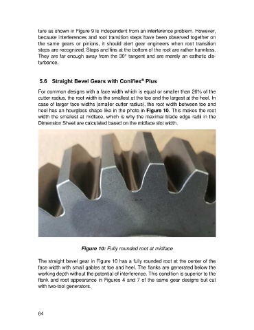
For common designs with a face width which is equal or smaller than 26% of the
cutter radius, the root width is the smallest at the toe and the largest at the heel. In
case of larger face widths (smaller cutter radius), the root width between toe and
heel has an hourglass shape like in the photo in Figure 10. This makes the root
width the smallest at midface, which is why the maximal blade edge radii in the
Dimension Sheet are calculated based on the midface slot width.
Figure 10: Fully rounded root at midface
The straight bevel gear in Figure 10 has a fully rounded root at the center of the
face width with small gables at toe and heel. The flanks are generated below the
working depth without the potential of interference. This condition is superior to the
flank and root appearance in Figures 4 and 7 of the same gear designs but cut
with two-tool generators.
64