
Page 76 - Gear Technology Solutions
P. 76
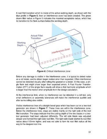
A root fillet transition which is inside of the active working depth, as shown with the
                   blue profile in Figure 5, then an interference zone has been created. The green
                   drawn fillet radius in Figure 5 indicates the maximal acceptable radius, which has
                   its transition to the flank surface below the working depth.


                                           Figure 6: Critical interference zone

                   Before any damage is visible in the interference zone, it is typical to detect noise
                   on a roll tester, and to obtain larger motion error than expected. Often interference
                   cannot be detected visually after rolling the gearset on a tester. In this case, a sin-
                   gle flank  test might  show  larger  than expected  errors.  A Fast  Fourier Transfor-
                   mation (FFT) of the single flank results will show a first harmonic amplitude which
                   is larger than the motion error amplitude from the design calculation.

                   At the interference limit, when no interference can be detected in a roll test, only
                   small deflections or assembly tolerances will make the interference audible and
                   after some rolling also visible.

                   Visible interference lines of a straight bevel gear which has been cut on a two-tool
                   generator are shown in Figure 7. These lines are within the interference zone.
                   Below the interference lines, steps are visible mainly on the right side of the root
                   fillet transition. The steps indicate that the cutting depth of the two blades in a two-
                   tool  generator  had  been  adjusted  differently.  The  left  side  blade  was  adjusted
                   deeper and formed the right-side root fillet. The right-side blade started its root fillet
                   radius about 0.5mm higher, and was not able to form its root fillet radius all the
                   way to the deepest root line.


                                                                                                      61