
Page 63 - Gear Technology Solutions
P. 63
direction. The motion graph has, next to some numerical entrance and exit var-
iation, zero motion error. The contact bearings show line contact within the en-
tire working area. The coast side contact ends at a toe root undercut (section
e).
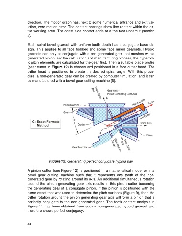
Each spiral bevel gearset with uniform tooth depth has a conjugate base de-
sign. This applies to all face hobbed and some face milled gearsets. Hypoid
gearsets can only be conjugate with a non-generated gear that meshes with a
generated pinion. For the calculation and manufacturing process, the hyperbol-
ic pitch elements are calculated for the gear first. Then a suitable blade profile
(gear cutter in Figure 12) is chosen and positioned in a face cutter head. The
cutter head is positioned to create the desired spiral angle. With this proce-
dure, a non-generated gear can be created by computer simulation, and it can
be manufactured with a bevel gear cutting machine [6].
Figure 12: Generating perfect conjugate hypoid pair
A pinion cutter (see Figure 12) is positioned in a mathematical model or in a
bevel gear cutting machine such that it represents one tooth of the non-
generated gear by rotating around its axis. An additional simultaneous rotation
around the pinion generating gear axis results in this pinion cutter becoming
the generating gear of a conjugate pinion. If the pinion is positioned with the
same offset that was used to determine the pitch surfaces (Figure 9), then the
cutter rotation around the pinion generating gear axis will form a pinion that is
perfectly conjugate to the non-generated gear. The tooth contact analysis in
Figure 11 has been obtained from such a non-generated hypoid gearset and
therefore shows perfect conjugacy.
48