
Page 47 - Gear Technology Solutions
P. 47
of contact. The marking compound thickness is drawn above the presentation
plane section. The point where the crowning curve exceeds the marking com-
pound thickness at both sides of the path of contact point determines the visi-
ble contact line length in the TCA. A typical value for the marking compound
thickness is 6mm. The tooth boundaries along top and root in Figure 5 (bottom
right side) limit the contact line length before the crowning curve can exit the
compound (e.g. contact lines No. 1 and 2) [5].
3.5 A Different Way to Generate an Ease-Off Graphic
There has been an attempt to represent the Ease-Off information in a different
form using ISO-lines. The idea is to have a two-dimensional graphic which
contains all the information about crowning or mismatch. This is a step back at
a time when CAD systems are all three-dimensional with easy to capture com-
plex shapes.
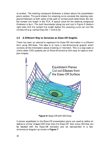
Figure 6: Ease-Off with ISO-lines
If planes equidistant to the Ease-Off presentation plane are used to define el-
liptical or similar shaped ISO-lines from the Ease-Off, then every ISO-line can
be labeled with the Ease-Off elevation and be represented in a two-
dimensional diagram as shown in Figure 7.
32