
Page 45 - Gear Technology Solutions
P. 45
The Ease-Offs in Figure 3 have no deviations in vertical direction, which is
consequently reflected in zero-motion graphs. This means that the transmis-
sion of rotation between pinion and gear follows exactly the ratio given by the
tooth count. The contact bearings are full and extend over the entire active
working area of the flanks.
Such a contact bearing is rather academic and cannot be used in a power
transmission. Tolerances in the gearbox housing, manufacturing deviations of
the gears, and load and heat inflicted deformations would quickly cause edge
contact and, therefore, a load concentration at the boundaries of the teeth.
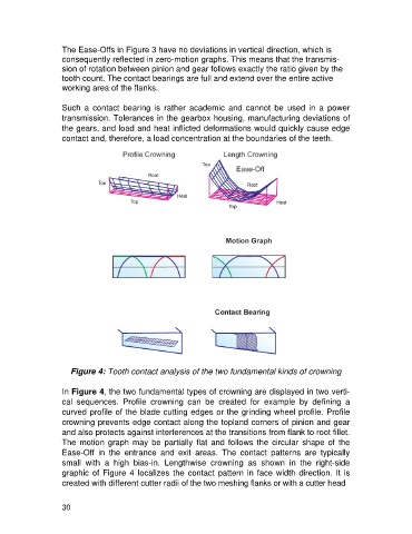
Figure 4: Tooth contact analysis of the two fundamental kinds of crowning
In Figure 4, the two fundamental types of crowning are displayed in two verti-
cal sequences. Profile crowning can be created for example by defining a
curved profile of the blade cutting edges or the grinding wheel profile. Profile
crowning prevents edge contact along the topland corners of pinion and gear
and also protects against interferences at the transitions from flank to root fillet.
The motion graph may be partially flat and follows the circular shape of the
Ease-Off in the entrance and exit areas. The contact patterns are typically
small with a high bias-in. Lengthwise crowning as shown in the right-side
graphic of Figure 4 localizes the contact pattern in face width direction. It is
created with different cutter radii of the two meshing flanks or with a cutter head
30