
Page 46 - Gear Technology Solutions
P. 46
tilt, which has the same effect. The motion graph may have a small flat area
where the path of contact is oriented in profile direction and follows the circular
shape of the Ease-Off in the entrance and exit areas.
3.4 How Contact Patterns are Calculated
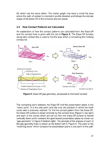
An explanation of how the contact patterns are calculated from the Ease-Off
and the contact lines is given with the aid of Figure 5. The Ease-Off function
along each contact line is used to find the area which is contacting the marking
compound.
Figure 5: Ease-Off gap geometry, processed to find tooth contact
The contacting point between the Ease-Off and the presentation plane is the
“mean point”. It is the only point (and the only roll position) in which the tooth
count ratio is precisely realized. To find the contact pattern from the Ease-Off,
the Ease-Off surface is sliced vertically by the contact lines (Figure 5, top right)
and each of the curves which are cut out from the Ease-Off surface is moved
vertically down until it contacts the gear-based presentation plane as shown as
“gap geometry” in Figure 5 (bottom right). The principle of the analysis of each of
the gap geometry lines is shown at the bottom left in Figure 5. The point of the
“crowning curve” which contacts the presentation plane is one point of the path
31