
Page 44 - Gear Technology Solutions
P. 44
For explanation purposes, the ring gear has only one tooth which is curved
and has a spiral angle. In order to show the Ease-Off deviation amounts on a
flat plane, the principle of the projection plane is introduced. As a projection
plane, an axis section plane is used where the tooth corner points of the teeth
are radially projected onto the section plane. The red square in Figure 2 repre-
sents the gear tooth with heel, toe, top and root. This projection plane is now
used to draw the Ease-Off deviations as a third dimension. If both mating bevel
gears have conjugate manufacturing data, then the Ease-Off graphic has no
deviations in ordinate direction. Also, if the pinion flanks and the gear flanks
have spiral angle errors of equal amounts, the Ease-Off graphic will not show
any deviation. Although the individual gears are considered incorrect in this
case, they will roll conjugate with each other, which subsequently leads to an
Ease-Off without any ordinate values. In case of length and profile crowning,
circular deviations will be visible in the third-dimension direction. It cannot be
determined in the Ease-Off graphic if the crowning was applied to the pinion or
to the gear, or if part of the crowning was applied to the pinion and another
part was applied to the gear.
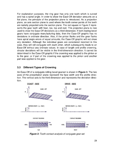
3.3 Different Types of Crowning
An Ease-Off of a conjugate rolling bevel gearset is shown in Figure 3. The two
axes of the presentation plane represent the face width and the profile direc-
tion. The vertical axis is the third dimension and represents the deviation direc-
tion.
Figure 3: Tooth contact analysis of conjugate gear set
29