
Page 450 - Gear Technology Solutions
P. 450
If the space left for blade top width is larger than the blade top width in Figure
20, then the Top width from Figure 20 is used. If the space left for top width is
smaller than the top width from Figure 20, then the new blade top width is used
for the new JOB1_AUX blade grinding summary (see Figure 21). In this case
the top width of 2.94mm is used. If the same cutter or grinding wheel should be
used for both pinion and gear, then the blade grinding summary with the
smallest point width has to be used.
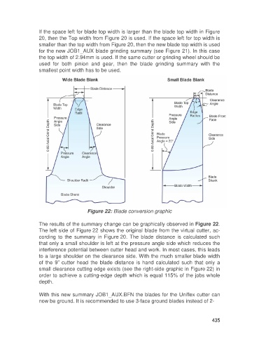
Figure 22: Blade conversion graphic
The results of the summary change can be graphically observed in Figure 22.
The left side of Figure 22 shows the original blade from the virtual cutter, ac-
cording to the summary in Figure 20. The blade distance is calculated such
that only a small shoulder is left at the pressure angle side which reduces the
interference potential between cutter head and work. In most cases, this leads
to a large shoulder on the clearance side. With the much smaller blade width
of the 9” cutter head the blade distance is hand calculated such that only a
small clearance cutting edge exists (see the right-side graphic in Figure 22) in
order to achieve a cutting-edge depth which is equal 115% of the jobs whole
depth.
With this new summary JOB1_AUX.BFN the blades for the Uniflex cutter can
now be ground. It is recommended to use 3-face ground blades instead of 2-
435