
Page 415 - Gear Technology Solutions
P. 415
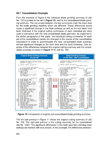
29.7  Consolidation Example

                   From the example of Figure  8  the individual blade grinding  summary  of Job
                   No. 102 is printed to the left in Figure 10, next to the consolidated blade grind-
                   ing summary. The red arrows between the two summaries mark the input data
                   for  the  blade  grinding  machine  which  are  different.  Those  differences  would
                   cause a significant change in the flank surfaces as well as the root depth and
                   tooth  thickness  if  the  original  cutting  summaries  of  each  individual  job  were
                   used in connection with the new consolidated blade geometry. As explained in
                   the earlier paragraphs of this paper, the individual cutting summaries for each
                   job of the consolidation variety are changed in the course of the consolidation
                   calculations in  order to accommodate  the new, consolidated blade summary
                   without significant changes to the flank form and the tooth thickness. One ex-
                   ample of the differences between the original cutting summary and the consol-
                   idated summary is shown in Figure 11 for Job No. 102.


                     Figure 10: Comparison of original and consolidated blade grinding summary

                   The left side printout in Figure 11 shows the original cutting summary of Job
                   No.  102.  The  right-side  printout  is  the  cutting  summary  for  the  consolidated
                   Job No. 102C. The significant differences in the tooth geometry defining basic
                   settings are marked with blue arrows. In this example, the differences between


                   400