
Page 393 - Gear Technology Solutions
P. 393
Now perform the probe alignment, the gage probe cycle and check the pre-
load of the probe as usual. During this procedure the adjustment screws of
the cutter head are not tight and may just slightly touch the blades. The
above steps conclude the probe zeroing cycle.
28.5 Measurement Cycle
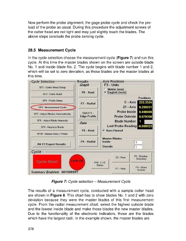
In the cycle selection choose the measurement cycle (Figure 7) and run this
cycle. At this time the master blades shown on the screen are outside blade
No. 1 and inside blade No. 2. The cycle begins with blade number 1 and 2,
which will be set to zero deviation, as those blades are the master blades at
this time.
Figure 7: Cycle selection – Measurement Cycle
The results of a measurement cycle, conducted with a sample cutter head
are shown in Figure 8. This chart has to show blades No. 1 and 2 with zero
deviation because they were the master blades of this first measurement
cycle. From the radial measurement chart, select the highest outside blade
and the lowest inside blade and make those blades the new master blades.
Due to the functionality of the electronic indicators, those are the blades
which have the largest radii. In the example shown, the master blades are
378