
Page 370 - Gear Technology Solutions
P. 370
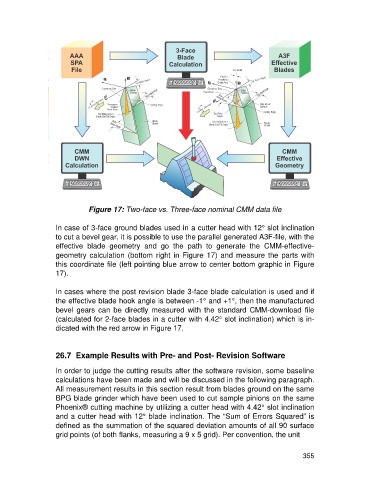
Figure 17: Two-face vs. Three-face nominal CMM data file

                   In case of 3-face ground blades used in a cutter head with 12° slot inclination
                   to cut a bevel gear, it is possible to use the parallel generated A3F-file, with the
                   effective  blade  geometry  and  go  the  path  to  generate  the  CMM-effective-
                   geometry  calculation (bottom right in Figure  17) and  measure the parts with
                   this coordinate file (left pointing blue arrow to center bottom graphic in Figure
                   17).

                   In cases where the post revision blade 3-face blade calculation is used and if
                   the effective blade hook angle is between -1° and +1°, then the manufactured
                   bevel  gears  can  be  directly  measured  with  the  standard  CMM-download  file
                   (calculated for 2-face blades in a cutter with 4.42° slot inclination) which is in-
                   dicated with the red arrow in Figure 17.


                   26.7  Example Results with Pre- and Post- Revision Software

                   In order to judge the cutting results after the software revision, some baseline
                   calculations have been made and will be discussed in the following paragraph.
                   All measurement results in this section result from blades ground on the same
                   BPG blade grinder which have been used to cut sample pinions on the same
                   Phoenix® cutting machine by utilizing a cutter head with 4.42° slot inclination
                   and a cutter head with 12° blade inclination. The “Sum of Errors Squared” is
                   defined as the summation of the squared deviation amounts of all 90 surface
                   grid points (of both flanks, measuring a 9 x 5 grid). Per convention, the unit


                                                                                                     355