
Page 369 - Gear Technology Solutions
P. 369
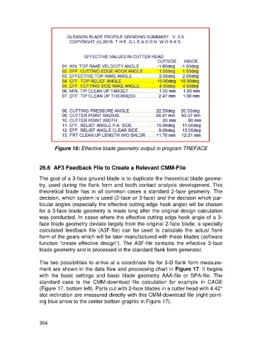
Figure 16: Effective blade geometry output in program TREFACE


                   26.6  AF3 Feedback File to Create a Relevant CMM-File

                   The goal of a 3-face ground blade is to duplicate the theoretical blade geome-
                   try, used during the flank form and tooth contact analysis development. This
                   theoretical blade  has in all common cases a standard 2-face  geometry.  The
                   decision, which system is used (2-face or 3-face) and the decision which par-
                   ticular angles (especially the effective cutting edge hook angle) will be chosen
                   for a 3-face blade geometry is made long after the original design calculation
                   was conducted. In cases where the effective cutting edge hook angle of a 3-
                   face blade geometry deviate largely from the original 2-face blade, a specially
                   calculated  feedback  file  (A3F-file)  can  be  used  to  calculate  the  actual  flank
                   form of the gears which will be later manufactured with these blades (software
                   function  “create  effective  design”).  The  A3F-file  contains  the  effective  3-face
                   blade geometry and is processed in the standard flank form generator.

                   The two possibilities to arrive at a coordinate file for 3-D flank form measure-
                   ment are shown in the data flow and processing chart in Figure 17. It begins
                   with  the  basic  settings  and  basic  blade  geometry  AAA-file  or  SPA-file.  The
                   standard  case  is  the  CMM-download  file  calculation  for  example  in  CAGE
                   (Figure 17, bottom left). Parts cut with 2-face blades in a cutter head with 4.42°
                   slot inclination are measured directly with this CMM-download file (right point-
                   ing blue arrow to the center bottom graphic in Figure 17).


                   354