
Page 368 - Gear Technology Solutions
P. 368
aborts after maximally 6 steps). The dampening factor and the number of
steps has been adjusted such that the overall system of loops works stable
and the final result in all evaluated cases are within the acceptable accuracy
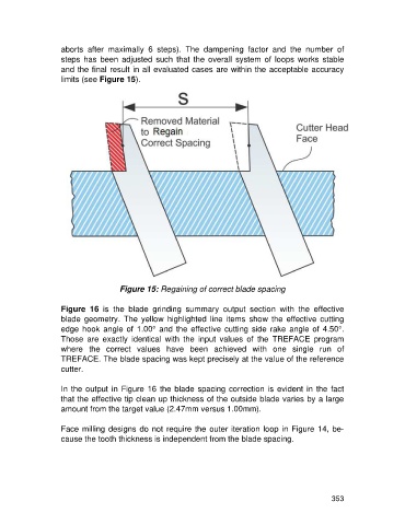
limits (see Figure 15).
Figure 15: Regaining of correct blade spacing
Figure 16 is the blade grinding summary output section with the effective
blade geometry. The yellow highlighted line items show the effective cutting
edge hook angle of 1.00° and the effective cutting side rake angle of 4.50°.
Those are exactly identical with the input values of the TREFACE program
where the correct values have been achieved with one single run of
TREFACE. The blade spacing was kept precisely at the value of the reference
cutter.
In the output in Figure 16 the blade spacing correction is evident in the fact
that the effective tip clean up thickness of the outside blade varies by a large
amount from the target value (2.47mm versus 1.00mm).
Face milling designs do not require the outer iteration loop in Figure 14, be-
cause the tooth thickness is independent from the blade spacing.
353