
Page 371 - Gear Technology Solutions
P. 371
“inch²” is used, even if the surface evaluation is done in metric units, like in the
present case.
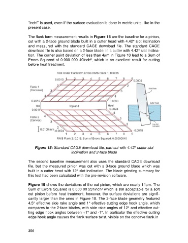
The flank form measurement results in Figure 18 are the baseline for a pinion,
cut with a 2-face ground blade built in a cutter head with 4.42° slot inclination
and measured with the standard CAGE download file. The standard CAGE
download file is also based on a 2-face blade, in a cutter with 4.42° slot inclina-
tion. The corner point deviation of less than 4mm in Figure 18 lead to a Sum of
2
Errors Squared of 0.000 000 40inch , which is an excellent result for cutting
before heat treatment.
Figure 18: Standard CAGE download file, part cut with 4.42° cutter slot
inclination and 2-face blade
The second baseline measurement also uses the standard CAGE download
file, but the measured pinion was cut with a 3-face ground blade which was
built in a cutter head with 12° slot inclination. The blade grinding summary for
this test had been calculated with the pre-revision software.
Figure 19 shows the deviations of the cut pinion, which are nearly 14mm. The
Sum of Errors Squared is 0.000 00 231inch² which is still acceptable for a soft
cut pinion before heat treatment, however, the surface deviations are signifi-
cantly larger than the ones in Figure 18. The 3-face blade geometry featured
4.5° effective side rake angle and 1° effective cutting edge hook angle, which
compares to the 2-face blades, with side rake angles of 12° and effective cut-
ting edge hook angles between +1° and -1°. In particular the effective cutting
edge hook angle causes the flank surface twist, visible on the concave flank in
356