
Page 314 - Gear Technology Solutions
P. 314
The GBX can measure and calculate corrections not only Two-Face Blades
like the No. 562, but also Three-Face Blades. Also blades for new methods,
such as CONIFLEX®, CONIFACE™ and PowerSkiving blades can be meas-
ured and corrected using the Gleason GBX [2].
22.4 Technological Blade Angles
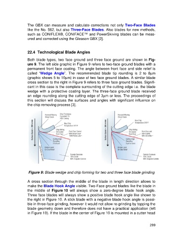
Both blade types, two face ground and three face ground are shown in Fig-
ure 9. The left side graphic in Figure 9 refers to two-face ground blades with a
permanent front face coating. The angle between front face and side relief is
called “Wedge Angle”. The recommended blade tip rounding is 2 to 8mm
(graphic shows 5 to 10mm) in case of two face ground blades. A similar blade
cross section to the right in Figure 9 refers to three face ground blades. Signifi-
cant in this case is the complete surrounding of the cutting edge i.e. the blade
wedge with a protective coating layer. The three-face ground blade received
an edge rounding along the cutting edge of 3mm or less. The proceedings of
this section will discuss the surfaces and angles with significant influence on
the chip removing process [3].
Figure 9: Blade wedge and chip forming for two and three face blade grinding
A cross section through the middle of the blade in length direction allows to
make the Blade Hook Angle visible. Two-Face ground blades like the blade in
the middle of Figure 10 will always show a zero-degree blade hook angle.
Three face blades will always show a positive blade hook angle like shown to
the right in Figure 10. A stick blade with a negative blade hook angle is possi-
ble in three-face grinding, however it would not allow re-grinding by topping the
blade geometry down and therefore does not have a practical application (left
in Figure 10). If the blade in the center of Figure 10 is mounted in a cutter head
299