
Page 319 - Gear Technology Solutions
P. 319
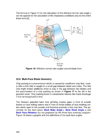
The formula in Figure 14 for the calculation of the effective normal rake angle g
                   can be applied for the calculation of the sharpness conditions around the entire
                   blade front [3].


                              Figure 16: Effective normal rake angles around blade front


                   22.6  Multi-Face Blade Geometry

                   Chip packing is a phenomenon which is caused by insufficient chip flow, most-
                   ly after a first chip is caught in a small gap between blade and cutter. The first
                   chip might initiate additional chips to stay in the gap between two blades and
                   the accumulation of  a chip  packing as shown  in Figure 17  to  the left is  the
                   possible result. Chip packing leads to catastrophic failures like blade breakage
                   if it is not recognized in time.

                   The  Gleason  patented  back  face  grinding  creates  gaps  in  front  of  outside
                   blades on face milling cutters and in front of inside blades of face hobbing cut-
                   ters which open to the outside and therefore promote a free chip flow. The pa-
                   rameter  for  the  back  faces,  Back  Rake  Angle e ,  Back  Hook  Angle  h  and
                   Back Face Distance DSF are proposed by the three-face summary program.
                   Figure 18 shows a graphic with the definitions of the back face angles.


                   304