
Page 316 - Gear Technology Solutions
P. 316
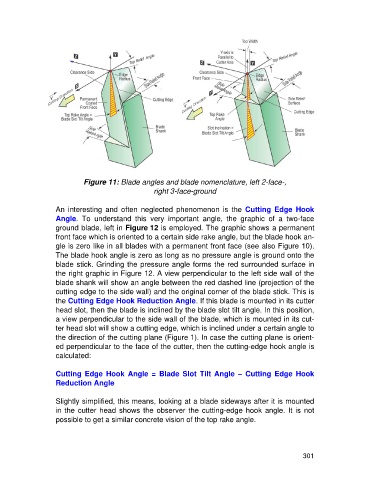
Figure 11: Blade angles and blade nomenclature, left 2-face-,
                                                    right 3-face-ground

                   An  interesting  and  often  neglected  phenomenon  is  the  Cutting  Edge  Hook
                   Angle.  To  understand  this  very  important  angle,  the  graphic  of  a  two-face
                   ground blade, left in Figure 12 is employed. The graphic shows a permanent
                   front face which is oriented to a certain side rake angle, but the blade hook an-
                   gle is zero like in all blades with a permanent front face (see also Figure 10).
                   The blade hook angle is zero as long as no pressure angle is ground onto the
                   blade stick. Grinding the pressure angle forms the red surrounded surface in
                   the right graphic in Figure 12. A view perpendicular to the left side wall of the
                   blade shank will show an angle between the red dashed line (projection of the
                   cutting edge to the side wall) and the original corner of the blade stick. This is
                   the Cutting Edge Hook Reduction Angle. If this blade is mounted in its cutter
                   head slot, then the blade is inclined by the blade slot tilt angle. In this position,
                   a view perpendicular to the side wall of the blade, which is mounted in its cut-
                   ter head slot will show a cutting edge, which is inclined under a certain angle to
                   the direction of the cutting plane (Figure 1). In case the cutting plane is orient-
                   ed perpendicular to the face of the cutter, then the cutting-edge hook angle is
                   calculated:

                   Cutting  Edge  Hook  Angle  =  Blade  Slot  Tilt  Angle  –  Cutting  Edge  Hook
                   Reduction Angle

                   Slightly simplified, this means, looking at a blade sideways after it is mounted
                   in the  cutter head  shows the  observer the  cutting-edge hook angle. It is  not
                   possible to get a similar concrete vision of the top rake angle.


                                                                                                     301