
Page 196 - Gear Technology Solutions
P. 196
13.8 First Example - 24-Tooth Coupling
After the basic settings are calculated, the UNICAL™ program can generate the
flank surfaces and even perform a tooth contact analysis. Although the clutch
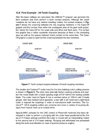
members do not have any relative meshing motion, the contact analysis in Fig-
ure 7 shows the crowning between the two coupling members in the Ease-Off
graphic and the contact lines within the overlapped area of the gear tooth projec-
tion below the Ease-Off for the coast side and drive side flank pairs. The contact
line graphic has a rather academic character because all lines in the contacting
area (as well as the spaces between them) contact at the same time. The Ease-
Off graphic is used to optimize the crowning between the two members.
Figure 7: Tooth contact analysis between 24-tooth coupling members
The double slot Cyclocut™ cutter head for the face hobbing clutch cutting process
is shown in Figure 8. The slots have prismatic bottom seating surfaces and posi-
tion the inside blade with a blade spacing angle of 5.6° behind the leading outside
blade. The cutter head in Figure 8 has a nominal radius of 125mm with 9 blade
groups. Like face hobbed bevel gearsets, a pair with a left hand and a right-hand
cutter is required for couplings in order to manufacture both members. The Cy-
clocut™ 125-9 coupling cutters are universal and cover a variety of coupling de-
signs from module 1mm up to module 5mm.
Special MMC software for the CNC control of Phoenix® machines has been de-
veloped in order to perform a plunging with the cutter head positioned at the first
set of V-H basic settings and then the cutter is moved with an interpolating motion
to the second set of V-H basic settings. Plunging and withdrawal are processed
along the work axial direction (in case of positive pressure angles).
181