
Page 191 - Gear Technology Solutions
P. 191
high speed dry cutting process. It was an important goal to preserve the original
geometry of the traditional face hobbed spiral face coupling.
The new process utilizes one right hand cutter head with inside and outside blades
for the manufacture of the right-hand coupling member and one left hand cutter
with inside and outside blades for the manufacture of the left hand coupling mem-
ber.
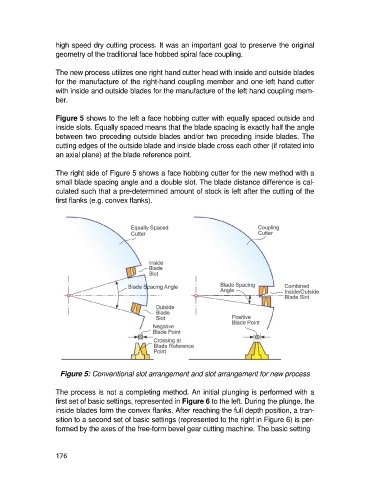
Figure 5 shows to the left a face hobbing cutter with equally spaced outside and
inside slots. Equally spaced means that the blade spacing is exactly half the angle
between two preceding outside blades and/or two preceding inside blades. The
cutting edges of the outside blade and inside blade cross each other (if rotated into
an axial plane) at the blade reference point.
The right side of Figure 5 shows a face hobbing cutter for the new method with a
small blade spacing angle and a double slot. The blade distance difference is cal-
culated such that a pre-determined amount of stock is left after the cutting of the
first flanks (e.g. convex flanks).
Figure 5: Conventional slot arrangement and slot arrangement for new process
The process is not a completing method. An initial plunging is performed with a
first set of basic settings, represented in Figure 6 to the left. During the plunge, the
inside blades form the convex flanks. After reaching the full depth position, a tran-
sition to a second set of basic settings (represented to the right in Figure 6) is per-
formed by the axes of the free-form bevel gear cutting machine. The basic setting
176