
Page 192 - Gear Technology Solutions
P. 192
transition includes a generating gear axis set-over rotation. At the end of this set-
over, the outside blades form the concave flanks. The cutter withdraws away from
the slots and both convex and concave flanks, as well as the slot bottoms, are fin-
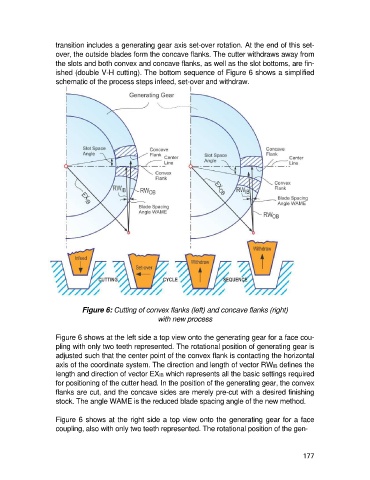
ished (double V-H cutting). The bottom sequence of Figure 6 shows a simplified
schematic of the process steps infeed, set-over and withdraw.
Figure 6: Cutting of convex flanks (left) and concave flanks (right)
with new process
Figure 6 shows at the left side a top view onto the generating gear for a face cou-
pling with only two teeth represented. The rotational position of generating gear is
adjusted such that the center point of the convex flank is contacting the horizontal
axis of the coordinate system. The direction and length of vector RWIB defines the
length and direction of vector EXIB which represents all the basic settings required
for positioning of the cutter head. In the position of the generating gear, the convex
flanks are cut, and the concave sides are merely pre-cut with a desired finishing
stock. The angle WAME is the reduced blade spacing angle of the new method.
Figure 6 shows at the right side a top view onto the generating gear for a face
coupling, also with only two teeth represented. The rotational position of the gen-
177