
Page 199 - Gear Technology Solutions
P. 199
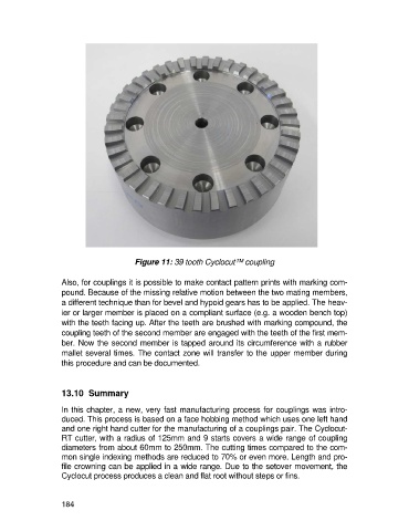
Figure 11: 39 tooth Cyclocut™ coupling

                   Also, for couplings it is possible to make contact pattern prints with marking com-
                   pound. Because of the missing relative motion between the two mating members,
                   a different technique than for bevel and hypoid gears has to be applied. The heav-
                   ier or larger member is placed on a compliant surface (e.g. a wooden bench top)
                   with the teeth facing up. After the teeth are brushed with marking compound, the
                   coupling teeth of the second member are engaged with the teeth of the first mem-
                   ber. Now the second member is tapped around its circumference with a rubber
                   mallet several times. The contact zone will transfer to the upper member during
                   this procedure and can be documented.


                   13.10  Summary

                   In this chapter, a new, very fast manufacturing process for couplings was intro-
                   duced. This process is based on a face hobbing method which uses one left hand
                   and one right hand cutter for the manufacturing of a couplings pair. The Cyclocut-
                   RT cutter, with a radius of 125mm and 9 starts covers a wide range of coupling
                   diameters from about 60mm to 250mm. The cutting times compared to the com-
                   mon single indexing methods are reduced to 70% or even more. Length and pro-
                   file crowning can be applied in a wide range. Due to the setover movement, the
                   Cyclocut process produces a clean and flat root without steps or fins.


                   184