
Page 198 - Gear Technology Solutions
P. 198
13.9 Second Example – 39-Tooth Coupling
The coupling for this example has an outer diameter of 140mm and a module of
3.0mm. The tooth face is 12mm wide and the pressure angle is 12.5°. The whole
depth of the coupling teeth in this example is equal to the module (3.0mm), which
is the typical stub tooth proportion for Cyclocut™ couplings. Compared to standard
bevel and hypoid gear teeth with a whole depth of 2.2 times the normal module
(depth factor = 1.00), the couplings use depth factors between 0.40 and 0.70
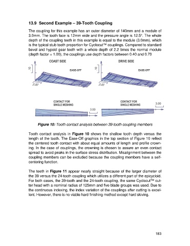
Figure 10: Tooth contact analysis between 39-tooth coupling members
Tooth contact analysis in Figure 10 shows the shallow tooth depth versus the
length of the tooth. The Ease-Off graphics in the top section of Figure 10 reflect
the centered tooth contact with about equal amounts of length and profile crown-
ing. In the case of couplings, the crowning is chosen to assure an even contact
spread to avoid peaks in the surface stress distribution. Misalignment between the
coupling members can be excluded because the coupling members have a self-
centering function.
The teeth in Figure 11 appear nearly straight because of the larger diameter of
the 39 versus the 24-tooth coupling which utilizes a different part of the epicycloid.
For both cases, the 39-tooth and the 24-tooth coupling, the same Cyclocut™ cut-
ter head with a nominal radius of 125mm and five blade groups was used. Due to
the continuous indexing, the index variation of the couplings after cutting is excel-
lent. However, there is no viable hard finishing method except hard skiving.
183