
Page 190 - Gear Technology Solutions
P. 190
The design of a typical bevel gear cutting machine with an interlocking cutter head
is shown in Figure 3. One part of the interlocking cutter arrangement carries the
inside blades, and the other part carries the outside blades. The cutting machine
has an imbedded double spindle arrangement where the inner spindle has a dif-
ferent center location versus the center location of the outer spindle. The radial
position of the two cutter centers has to be adjusted to accommodate a variety of
different coupling designs.
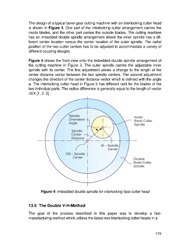
Figure 4 shows the front view onto the imbedded double spindle arrangement of
the cutting machine in Figure 3. The outer spindle carries the adjustable inner
spindle with its center. The first adjustment allows a change to the length of the
center distance vector between the two spindle centers. The second adjustment
changes the direction of the center distance vector which is defined with the angle
j. The interlocking cutter head in Figure 3 has different radii for the blades of the
two individual parts. The radius difference is generally equal to the length of vector
DEX [1, 2, 3].
Figure 4: Imbedded double spindle for interlocking face cutter head
13.5 The Double V-H-Method
The goal of the process described in this paper was to develop a fast-
manufacturing method which utilizes the latest non-interlocking cutter heads in a
175