
Page 189 - Gear Technology Solutions
P. 189
13.4 Solutions to Conflict No. 1 and Conflict No. 2
The generating gear in Figure 2 shows two face cutters, symbolized by the cutter
center vectors. The blade cutting edges are crossing initially at the blade reference
point but then receive radial corrections to accommodate the desired length
crowning. The cutter centers receive further corrections regarding their location to
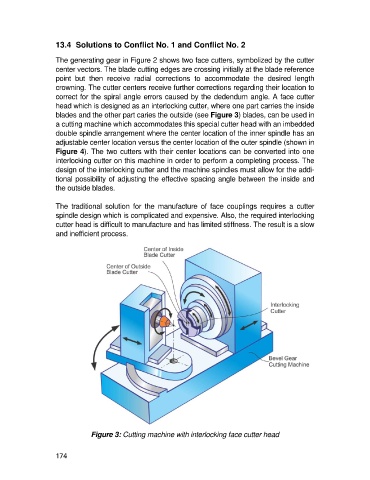
correct for the spiral angle errors caused by the dedendum angle. A face cutter
head which is designed as an interlocking cutter, where one part carries the inside
blades and the other part caries the outside (see Figure 3) blades, can be used in
a cutting machine which accommodates this special cutter head with an imbedded
double spindle arrangement where the center location of the inner spindle has an
adjustable center location versus the center location of the outer spindle (shown in
Figure 4). The two cutters with their center locations can be converted into one
interlocking cutter on this machine in order to perform a completing process. The
design of the interlocking cutter and the machine spindles must allow for the addi-
tional possibility of adjusting the effective spacing angle between the inside and
the outside blades.
The traditional solution for the manufacture of face couplings requires a cutter
spindle design which is complicated and expensive. Also, the required interlocking
cutter head is difficult to manufacture and has limited stiffness. The result is a slow
and inefficient process.
Figure 3: Cutting machine with interlocking face cutter head
174