
Page 185 - Gear Technology Solutions
P. 185
Curvic couplings are cut or ground with large cutter or grinding wheel diameters up
to 20”. The fixed Curvic coupling is used as a precise and stiff connection between
turbine rotors. The compressor and expansion rotors in nearly every jet engine are
connected with fixed Curvic couplings. Also, nearly all rotors in power plant steam
turbines are bolted together with fixed Curvic couplings. There is no alternative
solution to connect the high-speed rotors of gas, water and steam turbines. The
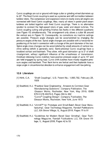
Curvic coupling cutting and grinding finishes two flanks in two different quadrants
(see Figure 15) simultaneously. This arrangement only allows a cutter tilt around
the vertical axis in Figure 15. Consequently, no corrections via machine settings
are possible. Pressure angle changes can be accomplished by changing the
pressure angles of the tool. Spiral angle changes are possible with a horizontal re-
positioning of the tool in connection with a change of the point diameter of the tool.
Spiral angle cross changes can be accomplished by small amounts of vertical ma-
chine setting (which is generally zero). Semi-universal Curvic couplings have a
localized contact and backlash. They allow, with good lubrication up to 2° of shaft
misalignment, without significant influence of the smoothness of transmission.
Overload releasing Curvic clutches have positive pressure angle of up to 10° and
are held engaged by spring load. Curvic shift clutches have mostly negative pres-
sure angles and backlash. Their flank forms are helical and their toplands have a
slope angle in circumferential direction to enhance engagement with low jerking.
12.6 Literature
[1] Hirth, C.A. “Shaft Couplings”, U.S. Patent No.: 1,660,792, February 28,
1928
[2] Stadtfeld, H.J. “Practical Gear Engineering - Answers to Common Gear
Manufacturing Questions”, Company Publication, The
Gleason Works, Rochester, New York, May 2019, ISBN
978-0-578-46376-6, Pages 355 to 362
®
[3] N.N. “Curvic Coupling Design”, Company Publication, The
Gleason Works, Rochester, New York, June 1973
[4] Stadtfeld, H.J. “Unimill™ for Prototype and Small-Batch Bevel Gear Manu-
facturing”, Gear Technology Magazine, Randall Publications
LLC, Elk Grove Village, IL, August 2018, Pages 70 to 81
[5] Stadtfeld, H.J. “Guidelines for Modern Bevel Gear Grinding”, Gear Tech-
nology Magazine, Randall Publications LLC, Elk Grove Vil-
lage, IL, August 2008, Pages 42 to 53
170