
Page 146 - Gear Technology Solutions
P. 146
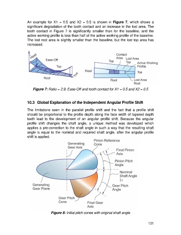
An  example  for  X1  =  0.5  and  X2  =  0.5  is  shown  in  Figure  7,  which  shows  a
                   significant degradation of the tooth contact and an increase in the lost area. The
                   tooth  contact  in  Figure  7  is  significantly  smaller  than  for  the  baseline,  and  the
                   active working profile is less than half of the active working profile of the baseline.
                   The lost root area is slightly smaller than the baseline, but the lost top area has
                   increased.


                       Figure 7: Ratio = 2.9, Ease-Off and tooth contact for X1 = 0.5 and X2 = 0.5


                   10.3  Global Explanation of the Independent Angular Profile Shift

                   The  limitations  seen  in  the  parallel  profile  shift  and  the  fact  that  a  profile  shift
                   should be proportional to the profile depth along the face width of tapered depth
                   teeth  lead  to  the  development  of  an  angular  profile  shift.  Because  the  angular
                   profile  shift  changes  the  shaft  angle,  a  unique  method  was  developed  which
                   applies a pre-correction to the shaft angle in such a way that the resulting shaft
                   angle is equal to the nominal and required shaft angle, after the angular profile
                   shift is applied.


                                   Figure 8: Initial pitch cones with original shaft angle


                                                                                                     131