
Page 143 - Gear Technology Solutions
P. 143
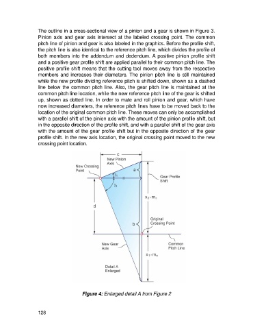
The outline in a cross-sectional view of a pinion and a gear is shown in Figure 3.
                   Pinion  axis  and  gear  axis  intersect  at  the  labeled  crossing  point.  The  common
                   pitch line of pinion and gear is also labeled in the graphics. Before the profile shift,
                   the pitch line is also identical to the reference pitch line, which divides the profile of
                   both members into the addendum and dedendum. A positive pinion profile shift
                   and a positive gear profile shift are applied parallel to their common pitch line. The
                   positive profile shift means that the cutting tool moves away from the respective
                   members and increases their diameters. The pinion pitch line is still maintained
                   while the new profile dividing reference pitch is shifted down, shown as a dashed
                   line below the common pitch line. Also, the gear pitch line is maintained at the
                   common pitch line location, while the new reference pitch line of the gear is shifted
                   up, shown as dotted line. In order to mate and roll pinion and gear, which have
                   now increased diameters, the reference pitch lines have to be moved back to the
                   location of the original common pitch line. These moves can only be accomplished
                   with a parallel shift of the pinion axis with the amount of the pinion profile shift, but
                   in the opposite direction of the profile shift, and with a parallel shift of the gear axis
                   with the amount of the gear profile shift but in the opposite direction of the gear
                   profile shift. In the new axis location, the original crossing point moved to the new
                   crossing point location.


                                         Figure 4: Enlarged detail A from Figure 2


                   128