
Page 142 - Gear Technology Solutions
P. 142
This is especially significant when the number of pinion and gear teeth is equal
(miter gears), or if the ratio is near one, like it is in the case of differential gears.
Miter gears therefore never receive a profile shift and differential gears only show
very small positive pinion profile shift coefficient (for example X1 = +0.15) because
the gear profile will develop undercut with the corresponding negative profile shift
coefficient (for example X2 = -0.15). Gearsets with larger ratios and a pinion tooth
count below 18 also require a profile shift and also in this case, only a limited V0
profile shift is possible. Figure 2 shows the tooth contact analysis of a straight
bevel gearset with a ratio of 2.9 without profile shift, which is used as a baseline in
the following sections. The tooth contact is very small in profile direction. The
number of pinion teeth is 12, which would require a profile shift to increase the
active working area, which is only about 50% of the available profile. The lost
areas at top and root are large due to physical pinion undercut and kinematic
undercut in the gear.
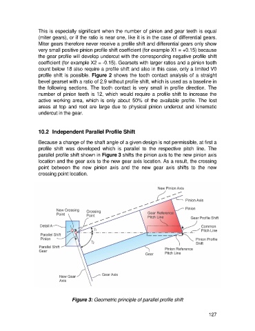
10.2 Independent Parallel Profile Shift
Because a change of the shaft angle of a given design is not permissible, at first a
profile shift was developed which is parallel to the respective pitch line. The
parallel profile shift shown in Figure 3 shifts the pinion axis to the new pinion axis
location and the gear axis to the new gear axis location. As a result, the crossing
point between the new pinion axis and the new gear axis shifts to the new
crossing point location.
Figure 3: Geometric principle of parallel profile shift
127