
Page 151 - Gear Technology Solutions
P. 151
As a result, the nominal and required shaft angle S 1 is re-established in
combination with the desired profile shift. The pitch lines of pinion and gear are not
congruent anymore, but the reference pitch lines of pinion and gear are congruent
and match the original pitch line. With this two-step approach, an angular profile
shift, which is proportional along the face width (direction ROUT) with the distance
from the crossing point, is the result. A proportional profile shift is adjusted to the
changing tooth depth between toe and heel. The profile shifts of pinion and gear
can be chosen individually and independently. There are no negative side effects
which would limit the amounts of proportional pinion and gear profile shifts.
Applying a global logic would deem that reducing the shaft angle by xj 1 + xj 2,
then calculating the new pitch angles and after that adding xj 1 + xj 2 to the
reduced shaft angle would arrive at the same tooth proportions as if the angular
profile shift was never applied. Despite this global logic, the pre-corrected pitch
angles sustain when the angular profile shift is added. The reason is that the
generating ratio (number of generating gear teeth divided by the number of work
gear teeth) remains when the profile shift is added, and the nominal shaft angle is
established. The pre-correction of the shaft angle in the first step (if X1+X2 >0)
reduces the mean diameter of pinion and gear, which also reduces the module.
The profiles of pinion and gear will sustain their characteristic because the
diameter as well as the module have been reduced by the same factor which will
maintain the root transitions and just result in a size reduction of the profiles. The
angular profile shift in the second step will then change the tooth profile according
to Figure 1.
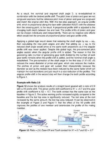
Example with Ratio 2.9
Figure 12 shows the analysis results of a straight bevel gearset with a ratio of 2.9
with a V0 profile shift. The pinion profile shift coefficient is X1 = +0.7 and the gear
profile shift coefficient is X2 = -0.7. The tooth contact has the same size as the
baseline in Figure 2. The active working profile increased slightly compared to the
baseline and the lost top area is significantly reduced. The lost area at the root
increased by the same amount, the lost top area reduced. It can be observed in
the example of Figure 2 and Figure 11 that the effect of the V0 profile shift
improves the profiles of one member and deteriorates the profile of the mating
member.
Figure 12: Ratio = 2.9, Ease-Off and Tooth contact for X1 = 0.7 and X2 = -0.7
136