
Page 135 - Gear Technology Solutions
P. 135
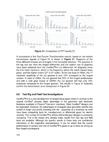
Figure 21: Comparison of FFT results [7]

                   A comparison of the Fast Fourier Transformation results, based on the motion
                   transmission  signals  of  Figure 16,  is  shown  in  Figure  21.  Diagrams  of  the
                   three different torques are arranged in the horizontal direction. The graphics in
                   the  top  row  are  from  the  forged  differential  and  the  bottom  row  of  graphics
                                                             ®
                   have been obtained from the Coniflex Pro cut differential. All diagrams  show
                   the first mesh harmonic, which is the frequency where the mesh impact takes
                                                     nd
                                                                                                        st
                                                            th
                   place, and the higher orders (2  to 6  order). At the low load of 10Nm, the 1
                   harmonic  amplitude  of  the  cut  gearset  is  only  10%  compared  to  the  forged
                   version. In case of 40Nm, the cut gearset has 20% of the forged predecessor
                   and  with  a  side  gear  torque  of  200Nm  the  cut  gearset  still  has  only  40%
                   amplitude compared to the forged gearset. The results in Figure 21 basically
                   confirm the transmission error comparison in Figure 20.


                   9.9  Test Rig and Field Test Investigations

                            ®
                   Coniflex Pro is a new development of straight bevel gears which in contrast to the
                                     ®
                   original  Coniflex   process  takes  advantage  of  the  geometric  and  kinematic
                                                   ®
                                                                                          ®
                   freedoms available in Phoenix  free-form machines. Older Coniflex  designs can
                   be duplicated. However, the advantages of conjugate base geometry and the free
                   control of length and profile crowning with the   possibility of a kinematic tip relief
                   have  been  compelling  facts  for  manufacturers  of  differential  gears  for  electric
                                                      ®
                   vehicles. The number of Coniflex Pro eDrive differential gear designs is constantly
                   increasing. This is the reason why already today results from test rigs and field
                   tests  are  available.  Although  the  specific  results  of  these  tests  are  confidential
                   information  of  the  respective  manufacturers,  it  can  be  stated  that  the  overall
                                                                 ®
                   performance of surface and root of Coniflex Pro gears is up to twice as strong as
                   their forged counterparts.


                   120