
Page 120 - Gear Technology Solutions
P. 120
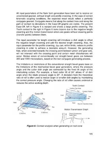
All input parameters of the flank form generation have been set to receive an
                   uncorrected gearset, without length and profile crowning. In the case of correct
                   kinematic  coupling  conditions,  the  expected  result  would  reflect  a  perfectly
                   conjugate gearset. Conjugate means that along the contact lines and along the
                   path of contact no deviations in the Ease-Off graphic are visible. The present
                   Ease-Off, left in Figure 6 is warped and shows a large profile crowning. The
                   Tooth contact to the right in Figure 6 looks bizarre due to the negative length
                   crowning and the motion transmission errors are peaks without crossing points
                   (transfer points) between them.

                   The input parameter for length crowning will introduce a dish angle to offset
                   the negative length crowning and add the desired length crowning. Also, the
                   input parameter for the profile crowning, Dg M can, within limits, reduce to profile
                   crowning  in  order  to  achieve  a  desirable  amount.  However,  the  generating
                   flats, when extended towards the crossing point between pinion and gear axis,
                   will  not  intersect  with  the  crossing  point  and  certain  mesh  disturbances  will
                   occur.  Motion  errors  of  conventionally  cut  straight  bevel  gears  are  between
                   300 and 1000 microradians, based on the non-conjugate generating process.

                   The limitations or restrictions of the conventional straight bevel gears base on
                   the  limitations  of  the  mechanical  bevel  gear  generators,  where  the  pressure
                   angle  and  the  cutter  dish  angle  are  connected  by  the  fixed  tilt  angle  of  the
                   interlocking  cutters.  For  example,  a  fixed  cutter  tilt  of  24°  allows  4°  of  dish
                   angle when the blade pressure angle is 20°. A deviation from the theoretical
                   ratio of roll is often used to realize larger or smaller dish angles by maintaining
                   the correct pressure angle. Changing the ratio of roll often causes undercut or
                   reduces the active working depth.


                               Figure 6: Contact analysis when generating on root cone


                                                                                                     105