
Page 98 - Gear Technology Solutions
P. 98
A typical single flank variation of a ground gearset is shown in Figure 6. The
graphic shows a harmonic deviation over one gear revolution and three har-
monic waves from the three pinion revolutions. The high frequency content is
created by the tooth mesh which repeats in the graphic 30 times.
The influence of the hunting tooth is not an academic effect which in theory
would improve the performance of a gear pair. To the contrary, there is a very
simple and very easy detectable practical difference between a gearset with a
hunting tooth and a gear-set with a common tooth count denominator. This dif-
ference becomes tangible during the gearset’s break-in.
Independent from the fact that if a gearset is ground, honed, lapped or not
hard-finished at all, there are certain flank form deviations from tooth to tooth
and there is an indexing error. The break-in will go a quite different path in
case of integer ratios. In the case of a 10x30 ratio, the three sections of the
larger gear will mesh with the 10 slots of the pinion. Teeth 1, 11 and 21 will
therefore only contact slot one of the pinion. During the break-in period, teeth
1, 11 and 21 will become similar or even equal to each other. The pinion teeth
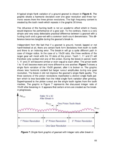
1 to 10 will become more and more different to one another. Figure 7 shows a
single flank variation of the 10x30 gearset, after it is broken in. The graphic
shows less harmonic content but larger runout amplitudes during one gear
revolution. The break-in did not improve the gearset’s single flank quality. The
three sections of the pinion revolutions manifested a distinct single flank pat-
tern which is less favorable than the initial single flank variation after grinding.
Superimposed to the pinion runout are the single tooth ripples from the tooth
meshes. The graphic in Figure 7 represents the discussed integer ratio of
10x30 after breaking in. It appears that certain errors are created as the break-
in progresses.
Figure 7: Single flank graphic of gearset with integer ratio after break-in
83