
Page 463 - Gear Technology Solutions
P. 463
the Clearance Angle in cases where the blade width leaves not much room for
the entire blade profile.
The values in the section “C B N GRINDING WHEEL DESIGN DATA” are
submitted to Gleason for the design of a CBN grinding wheel, if either grinding
from solid or grinding as hard finishing operation are the intended manufactur-
ing processes.
30.8 Cutter Building and Grinding Wheel Preparation
®
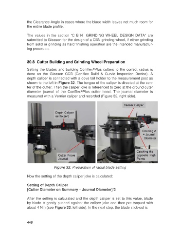
Setting the blades and building Coniflex Plus cutters to the correct radius is
done on the Gleason CCB (Coniflex Build & Curvic Inspection Device). A
depth caliper is connected with a dove tail holder to the measurement post as
shown to the left in Figure 32. The tongue of the caliper is directed at the cen-
ter of the cutter. Then the caliper joke is referenced to zero at the ground outer
®
diameter journal of the Coniflex Plus cutter head. The journal diameter is
measured with a Vernier caliper and recorded (Figure 32, right side).
Figure 32: Preparation of radial blade setting
Now the setting of the depth caliper joke is calculated:
Setting of Depth Caliper =
[Cutter Diameter on Summary – Journal Diameter]/2
After the setting is calculated and the depth caliper is set to this value, blade
by blade is gently pushed against the caliper joke and then pre-torqued with
about 4 Nm (see Figure 33, left side). In the next step, the blade stick-out is
448