
Page 458 - Gear Technology Solutions
P. 458
engineer can improvise and alter the values in case problems are encoun-
tered.
Because the smaller cutter uses blades with a smaller width, it might be diffi-
cult to fit the axial grind depth on the blade. The CONIBLD blade grinding
summary program uses for the Blade Distance the real blade tip thickness
+ 0.5mm. For face gears, the top width and the real blade tip thickness from
the original design summary remain unchanged which results in a Blade Dis-
tance = 1.92 + 0.5 = 2.42mm.
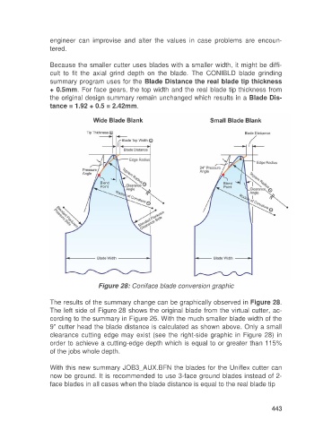
Figure 28: Coniface blade conversion graphic
The results of the summary change can be graphically observed in Figure 28.
The left side of Figure 28 shows the original blade from the virtual cutter, ac-
cording to the summary in Figure 26. With the much smaller blade width of the
9” cutter head the blade distance is calculated as shown above. Only a small
clearance cutting edge may exist (see the right-side graphic in Figure 28) in
order to achieve a cutting-edge depth which is equal to or greater than 115%
of the jobs whole depth.
With this new summary JOB3_AUX.BFN the blades for the Uniflex cutter can
now be ground. It is recommended to use 3-face ground blades instead of 2-
face blades in all cases when the blade distance is equal to the real blade tip
443