
Page 464 - Gear Technology Solutions
P. 464
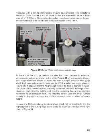
measured with a dish tip dial indicator (Figure 33, right side). The indicator is
                   zeroed at blade number 1 and all other blades are adjusted to within a toler-
                   ance of +/- 0.008mm. The axial cutting edge runout can be measured, howev-
                   er it doesn’t have to be trued if the runout is between +/-0.010mm.


                                    Figure 33: Radial blade setting and radial truing

                   At the  end  of the  build  procedure,  the  effective cutter  diameter is measured
                   with a vernier caliper as shown to the left in Figure 34 on two opposite blades.
                   The  cutter  reference  height  is  measured  with  a  height  measurement  gage
                   which  had  been  referenced  to  zero  on  the  CCB  spindle  face  (right  photo  in
                   Figure 34). It appears that the height gage will not be able to capture the posi-
                   tion of the blade reference point precisely because it contacts the edge radius.
                   However,  each  Coniflex  cutting  and  grinding  summary  has  a  pre-calculated
                   reference height correction item. The machine control uses this small number
                   in order  to  improve  the accuracy  of the  measured  cutter or  wheel  reference
                   height.

                   In case of a Uniflex cutter or grinding wheel, it will not be possible to find the
                   highest point of the cutting edge at the blade tip region as indicated in the right
                   photo of Figure 34.


                                                                                                     449