
Page 454 - Gear Technology Solutions
P. 454
Blade Distance =
Blade Width–0.88•Axial Grind Depth•tan(Blade Pressure Angle)
In the Example: Blade distance = 12.7–0.88•28.90•tan(20°) = 3.44mm
Space left for top width = 3.44 – 0.5 = 2.94mm
If the space left for blade top width is larger than the blade top width in Figure
23, then the Top width from Figure 23 is used. If the space left for top width is
smaller than the top width from Figure 23, then the new blade top width is used
for the new JOB1_AUX blade grinding summary (see Figure 24). In this case
the top width of 2.94mm is used. If the same cutter or grinding wheel should be
used for both pinion and gear, then the blade grinding summary with the
smallest point width has to be used.
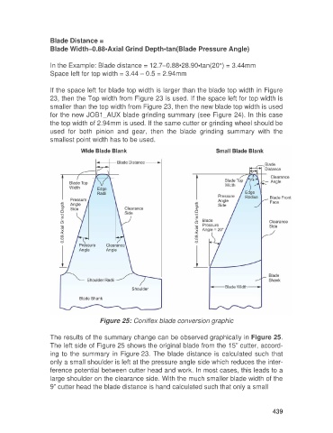
Figure 25: Coniflex blade conversion graphic
The results of the summary change can be observed graphically in Figure 25.
The left side of Figure 25 shows the original blade from the 15” cutter, accord-
ing to the summary in Figure 23. The blade distance is calculated such that
only a small shoulder is left at the pressure angle side which reduces the inter-
ference potential between cutter head and work. In most cases, this leads to a
large shoulder on the clearance side. With the much smaller blade width of the
9” cutter head the blade distance is hand calculated such that only a small
439